Configure Automatic Top-Off (ATO)
Reading time: ~15 minutes · Execution time: ~20 minutes · Audience: anyone who completed guide 05 and has at least one smart plug and one level sensor already configured
🟡 Important Guide — a feature that almost everyone will want to activate. Without it, the system works but is much less effective.
🗺️ Your JoyReef Path:
- Shopping list
- Controller assembly
- Firmware + WiFi
- Tank and sensor configuration
- Tasmota smart plugs
- Automatic Top-Off (ATO) ← YOU ARE HERE
- Temperature
- Water change
- Advanced automations
1. What you are about to do
ATO (Automatic Top-Off) is the first — and probably most useful — of the JoyReef automations. It serves to replace the fresh water that evaporates from your marine tank, maintaining constant salinity and level.
In a reef tank, fresh water evaporates continuously (leaving the salt behind). Without an ATO, you have to top off by hand, almost every day: forgetting for a week means crazy salinity, exposed heaters, and skimmers out of tune.
With the ATO configured, the portal keeps an eye on the water level through a float switch in the sump. When the level drops below the threshold, it turns on a top-off pump (connected to a Tasmota smart plug) for a few seconds, which pumps RODI water from a reservoir. When the level returns, it turns it off. All automatic, 24/7.
In this guide, you will configure:
- The level sensors (one mandatory minimum, one optional but highly recommended safety maximum)
- The top-off pump (= the smart plug you configured in guide 05)
- The safety limits (max time the pump can stay on, max per day, pause between cycles)
- Advanced automations (optional): pre-packaged routines to orchestrate start/stop/safety
2. What you need
Before starting, you must have already configured:
- ✅ A primary tank on the portal (you set this up in guide 04)
- ✅ At least one level sensor connected to the controller and assigned to a "level function" (
ATO operating level,Sump - Minimum level, etc.). See guide 04, sensors section - ✅ A Tasmota smart plug configured, online, and assigned to the tank (see guide 05)
- ✅ A top-off pump already connected to the smart plug (the classic 5-10W AC pump that draws from the osmosis reservoir)
- ✅ A RODI water reservoir full, with the pump's intake submerged and the output positioned in the sump
💡 Recommended (not mandatory): dual sensors. ATO with only one level sensor (the "minimum") works, but has no mechanical safety net: if the minimum sensor gets stuck (hair, biofilm, crystallized salt), the pump starts and never stops until it hits the max daily limit or the dosing timeout. With a second "maximum" sensor positioned 1-2 cm above the minimum, the system can stop the pump even if the main sensor fails.
💡 Have more than one level sensor? You can have ATO + water change + skimmer full + osmosis reservoir all monitored. In this guide, you configure only the ATO; other automations have dedicated guides (08 for water change, others coming soon).
3. How Automatic Top-Off works
Before touching the configuration page, take two minutes to understand the logic: it will help you avoid setting random values or getting scared by the first "lockout" you see.
The basic principle
The system is a very simple loop that runs on the physical controller (not on the portal: this is important, it works even if internet goes down):
every N seconds:
    if the minimum sensor says "low water" for at least X seconds:
        turn on the pump
        wait for the sensor to say "water ok" again
        turn off the pump
        wait Y seconds before checking again (lockout)
The parameters (X, Y, and several others) are configured on the page. Let's look at them all, as each has a specific safety purpose.
The 3 levels of safety
ATO is the "riskiest" system of all automation: if it goes wrong, you empty your osmosis reservoir into the tank (= salinity shock → corals die). For this reason, there are three overlapping safety filters:
1. Limit per single dosing (max_dose)
Maximum time the pump can stay on in a single cycle. If it exceeds this, the system goes into "fault" and stops until you unlock it manually.
Typical: 60-180 seconds.
Purpose: block the pump if the minimum sensor is stuck "low" and never returns to "ok."
2. Daily limit (max_daily)
Total time the pump can work in 24 hours. If exceeded, fault.
Typical: 600-1800 seconds (10-30 total minutes).
Purpose: block the system if there is a small continuous leak (e.g., sump tap dripping): the pump would top off for hours without realizing it.
3. Lockout between cycles (lockout)
Minimum pause between one stop and the next start. Even if the sensor immediately says "I still have low water," the system waits.
Typical: 30-120 seconds.
Purpose: give the newly pumped water time to stabilize in the sump (waves from the return pump cause the float switch to oscillate).
What happens in case of a fault
If one of the limits is triggered, you will see on the portal (and on the controller) the status "LOCKED FOR SAFETY" with the reason for the fault:
MAX LEVEL reached→ the upper safety sensor triggered (= the minimum sensor didn't stop the pump, and the water rose too much)DOSING TIMEOUT→max_doseexceededDAILY LIMIT→max_dailyexceededSENSOR ABSENT→ the minimum sensor is not sending data to the controller
In all these cases, the pump remains off and you must click "Unlock now" after understanding why. Do not unlock blindly: if you unlock without resolving the cause, the fault will return within seconds, and in the meantime, you might have pumped more liters into the tank.
4. Step 1 — Open the ATO page
From the JoyReef portal:
- Open portal.joy-reef.com and log in
- In the left menu, click on the "ATO" item (water pump icon 💧)
- Or go directly to
portal.joy-reef.com/ato
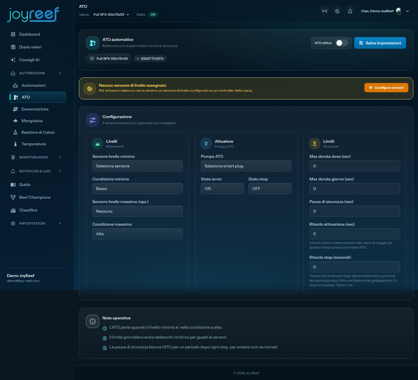
The "ATO" page opens with various boxes. If an orange banner appears at the top saying "Tank not selected" → go back to guide 04 and set a tank as primary, then return here.
If an orange banner appears saying "No level sensor assigned" → go back to guide 04 sensor section and assign at least one sensor to the role ATO operating level (or equivalent). ATO cannot function without it.
5. Step 2 — Configure level sensors
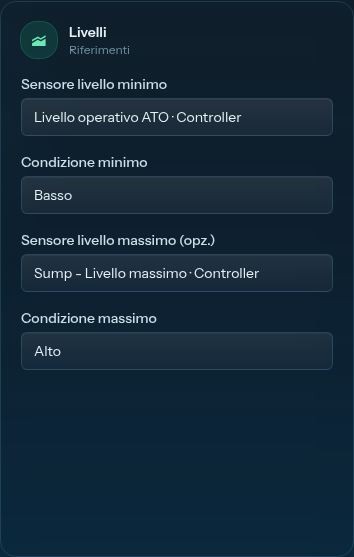
In the first card "Levels," you find 4 fields:
Minimum level sensor (mandatory)
The float switch that detects when water has dropped enough to start the top-off. Typically positioned in the sump, where the level drops first (because evaporation "discharges" the sump surface).
In the "Minimum level sensor" menu, select the level sensor you assigned as ATO operating level (or Sump - Minimum level if you chose that role). You'll recognize it by the controller name next to it (e.g., "ATO operating level · Main Controller").
Minimum condition
Float switches can behave in two ways depending on the model:
- "Low" = the sensor signals "LOW" when water drops below the float (normally open, closes when it emerges from the water)
- "High" = the sensor signals "HIGH" when water drops (normally closed, opens when it emerges)
In practice: try manually raising and lowering the float with the tank full, see what changes in the "Sensors" section of the portal, and choose the condition that corresponds to "low water."
💡 In doubt? Leave it as "Low" and test: if the pump starts when it shouldn't (tank full), come back here and change it to "High."
Maximum level sensor (optional, but highly recommended)
This is the safety net: a second float switch positioned 1-2 cm above the minimum. Its only function is to say "STOP" if water reaches it — meaning the minimum didn't work and we are already beyond the operating level.
In the "Maximum level sensor" menu, select the sensor you assigned as Sump - Maximum level (or ATO operating level if you have a single dual float with two contacts).
If you don't have a second float switch, leave it as "None": the ATO will still work, but you'll only be protected by the time/quantity limits (see section 7).
Maximum condition
Same logic as the minimum: choose the condition that corresponds to "water too high." Typically "High": the sensor signals "HIGH" when the water lifts it.
6. Step 3 — Choose the top-off pump
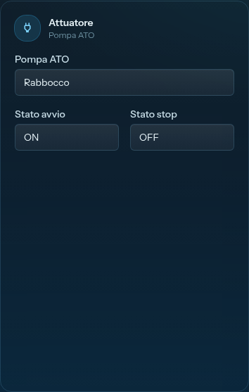
In the second card "Actuator":
ATO Pump
In the "ATO Pump" menu, select the smart plug to which you connected the top-off pump. The menu shows all smart plugs assigned to your tank (= those you configured in guide 05).
If the menu is empty or you don't see the right plug:
- The plug is not assigned to the current tank → go to Config → Devices, open the plug, check the "Tank" field
- The plug is offline or has never sent data → check the status indicator on the devices page
Start state / Stop state
These two menus tell the system what the "on state" of your pump is relative to the smart plug. In 99% of cases:
- Start state:
ON - Stop state:
OFF
That is: to turn on the pump, we send ON to the plug; to turn it off, OFF. Leave the defaults unless you have a strange configuration (e.g., pump driven by an inverted relay).
7. Step 4 — Set safety limits
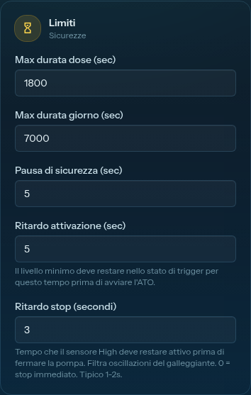
In the third card "Limits," you find 5 numerical fields. All in seconds.
Recommended values for a typical sump (~50 liter sump for a 200L net tank) with a standard AC top-off pump (5-10 W, ~80 L/h):
| Field | Recommended Value | Purpose |
|---|---|---|
| Max dose duration | 120 (= 2 min) |
The pump draws ~2.5L in 2 minutes, enough to top off 1-2 cm of evaporation in the sump. If the level doesn't return in 2 minutes, there's a problem |
| Max daily duration | 1200 (= 20 min) |
Total 20 min/day = ~25L of RODI water per day, well above typical evaporation. If you exceed this, there's a leak |
| Lockout | 60 (= 1 min) |
After each stop, wait 1 min before it can restart: newly pumped water stabilizes in the sump |
| Activation delay | 5 |
The minimum sensor must say "low" for at least 5 consecutive seconds before starting the pump. Filters false positives from wave oscillations |
| Stop delay | 2 |
The maximum sensor must say "high" for 2 consecutive seconds before stopping the pump (anti-oscillation) |
How to calibrate for your specific tank
If your tank is much smaller/larger, or the pump much more/less powerful, recalibrate:
max_dose= "how many seconds of pump are needed to recover 1 cm of level in the sump"? Measure once by hand, then double it. For powerful pumps (> 200 L/h),30-60seconds might be enough.max_daily= "how much water evaporates in 24h at MAXIMUM"? Measure for 2-3 days noting the sump level before and after. Set triple the measured evaporation.lockout= "how much time does water need to stabilize?" If the return pump is large and makes strong waves, increase to120-180.
⚠️ DO NOT set
max_dose = 0ormax_daily = 0: zero means "no limit," and you remove your protections. Even if you are sure of your configuration, always leave sensible values: they will save your aquarium the day a sensor fails.
8. Step 5 — Activate ATO and save
You have filled out all three cards. Now:
Step 1: activate the toggle
In the top right of the "Configuration" section, you'll find the "ATO active" toggle. Click it to activate (it becomes green).
Step 2: save
At the top of the page, next to the "Automatic ATO" title, is the "Save settings" button. Click it.
A green confirmation banner appears below: "ATO settings saved and sent to controllers."
In a few seconds, the controller receives the new configuration and starts monitoring the sensor. From this moment, the system is operational 24/7.
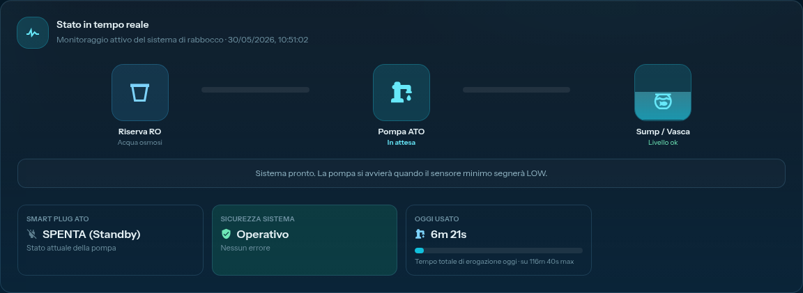
Step 3: verify the real-time monitor
Immediately after saving, a new section "Real-time status" appears with 4-5 boxes:
- ATO Smart Plug — current state (OFF in standby, ACTIVE during dosing)
- System Safety — OPERATIONAL or ANOMALY DETECTED
- Today used — total dosing seconds since midnight
- Last update — when the controller sent the last update
If you see a large green dot next to "DOSING IN PROGRESS" or blue next to "WAITING (Standby)," the system is working. ✅
If you see a red dot with "FAULT: ..." on first start, go to the "If something goes wrong" section further down.
9. Step 6 (optional) — Create advanced automations
Under the "Operational notes" card, you'll find an "Advanced automations" section with a "Create automations" button.
What it does: generates a series of ready-to-use routines (visible in the Automations page) that handle:
- Notifying via email if the ATO goes into fault
- Logging every dosing as an event (visible in the timeline)
- Turning off the skimmer for a few minutes after each top-off (useful if new water makes the skimmer "over-boil")
Do you have to do it? No, it's optional. The ATO pump works perfectly without them. Create the automations only if you want the extra behaviors above.
For now, you can skip this step and create them in the future when you are more familiar. You will always find them here.
💡 The created automations are editable. Once you click "Create automations," you can find the routines on the Automations page and adapt them as you like (change email recipients, thresholds, etc.). They are not "carved in stone."
10. Verify that it really works
Settings are saved, the monitor says "Operational." But does it really work? Let's do an active test.
Test 1: manual sensor simulation
- Temporarily remove the minimum float switch from its bracket in the sump (carefully, without turning anything off)
- Hold it up (= dry sensor = "low" state = ATO trigger)
- Wait 5-10 seconds (the "activation delay" + controller cycle time)
-
You should hear the pump start, and in the portal monitor see "DOSING IN PROGRESS" + green dot
-
Lower the float switch back to the operating position
- The pump stops after 1-2 seconds (the "stop delay")
- In the monitor you see "WAITING (Standby)" and total seconds in the "Today used" box
If this test works, the ATO is operational. ✅
Test 2 (if you have the maximum sensor): failsafe test
- Remove the minimum float switch and hold it up (the pump starts)
- Immediately after, also remove the maximum one and hold it up (= simulates "water too high")
- The pump stops immediately, and the system goes into "FAULT: MAX LEVEL"
-
In the monitor, the orange banner "Top-off is locked for safety" appears with the "Unlock now" button
-
Lower both float switches back to operating positions
- Click "Unlock now"
- The system returns to "WAITING." ✅
You have just verified that the safety net really works. It's worth ten minutes of your time.
⚠️ After the test, recheck that the float switches are in the correct operating position and that the system sees the water. If you have doubts, follow the sensor in real-time from the Sensors page for a few minutes.
11. If something goes wrong
The pump starts immediately and doesn't stop (with full sensor)
The minimum condition is inverted: the system thinks "high" is "low" or vice versa.
Go back to the ATO page "Levels" section and change "Minimum condition" (if it was "Low," set it to "High" and vice versa). Save. Try again.
It never starts, even when moving the float switch
Possible causes, in order of probability:
- ATO is not active → check the "ATO active" toggle above the configuration (must be green)
- The sensor is not sending data to the controller → go to Sensors, see if the float switch value changes when you move it by hand. If it doesn't, it's a wiring problem (see guide 04)
- You are looking at the wrong sensor → check in the "Levels" card which sensor you selected as minimum
- The controller is offline → look at the status dot in the "Real-time status" section. If red → controller offline, go to Devices
"FAULT: DOSING TIMEOUT" on first activation
max_dose set too low, or the pump can't recover the level in that time.
Diagnosis:
- Is the pump tap open? Sometimes tubes are clogged or kinked
- Is the osmosis reservoir empty? The pump is running dry, not moving water
max_dosetoo low? For a large tank with a weak pump, 60-120 seconds might not be enough. Unlock, increase to 180-300, and try again
"FAULT: MAX LEVEL" immediately
The upper safety sensor sees "high water" from the start. Possible causes:
- Wrong positioning of the maximum sensor: it must be 1-2 cm ABOVE the minimum, not below
- Maximum condition inverted: same reasoning as the minimum, try changing it
- Sensor faulty/fouled: check by hand
"FAULT: SENSOR ABSENT"
The controller doesn't receive data from the minimum sensor for more than a few minutes.
- Check the float switch cable (terminals firmly secured)
- Reboot the controller (unplug for 10 sec, replug)
- Verify in the Sensors page that the value arrives in real-time
"FAULT: DAILY LIMIT"
In 24 hours, the pump has worked more than allowed. Almost always means a leak or minimum sensor stuck "low".
- Check the sump for excess new water compared to normal (= minimum sensor oscillating randomly)
- Search for leaks in the system (sump pipes, fittings, skimmer)
- Do not unlock blindly: if you have a leak, unlocking will top off more water
Real-time monitor says "Controller offline"
Go to guide 04, controller troubleshooting. ATO cannot function if the controller doesn't talk to the portal (worse: it will continue to run locally on the controller, but you won't see states and won't be able to unlock faults).
12. Next step
Do you have the ATO operational and tested? Perfect. Your tank now tops itself off.
The next natural automations to tackle are:
➡️ Guide 07 — Temperature control (heater + fan, hysteresis, alerts)
➡️ Guide 08 — Automatic water change (drain pump + fill pump, weekly scheduling)
Both follow the same conceptual logic as the ATO: sensor → threshold → actuator → safety. Once you understand ATO, the others are faster.
💡 Let the ATO run for a few days before moving on to something else. Verify in the event timeline (Events menu) that it starts every 6-12 hours with short doses (30-60 sec). If you see continuous doses or strange cycles, return to the configuration and recalibrate before adding other automations.