First start: assemble the controller
Reading time: ~15 minutes · Execution time: 30-45 minutes · Audience: anyone who just received the components from the shopping list
🟢 Fundamental Guide — mandatory onboarding path. Without it, the system will not start.
🗺️ Your JoyReef Path:
- Shopping list
- Controller assembly ← YOU ARE HERE
- Firmware + WiFi
- Tank and sensor configuration
- Tasmota smart plugs
- Automations (ATO, etc.)
1. What you need on the table
Open the packages and arrange on the table:
- NodeMCU (the board with WiFi)
- Screw shield board (the base with screw terminals)
- DS18B20 temperature probe
- 4.7 kΩ Resistor
- 128×32 OLED Display
- Float switches (4 pieces)
- Cable set (M/F and M/M jumpers)
- Micro-USB cable (data cable, not just charging)
- USB Power Supply (phone charger, 5V 2A)
- A computer or phone to check that everything works afterward
You also need:
- A small Phillips screwdriver (0 or 00) to tighten the board terminals
- A pair of scissors to shorten cables if needed
- Optional: a wire stripper (though with some patience it can be done with scissors)
💡 No soldering iron, no hot glue, no special tools. If you have everything above, you're ready.
2. Get to know the NodeMCU
The NodeMCU is the blue board with the WiFi module on top. It has many pins along the two long sides, each with a name printed next to it (e.g., D5, D6, 3V3...). We only need 9: we ignore the others.
Here is the map of the pins we will use, grouped by function:
| Pin | What it's for |
|---|---|
3V3 |
Power for sensors (3.3 volts) |
GND |
Ground (the current "return", always present in every connection) |
D5 |
DS18B20 temperature probe |
D3 |
OLED Display — "data" pin (SDA) |
D4 |
OLED Display — "clock" pin (SCL) |
D6 |
Float switch 1 |
D7 |
Float switch 2 |
D1 |
Float switch 3 |
D2 |
Float switch 4 |
💡 Just keep the names in mind: on the screw shield board, next to each terminal, you will find the same name printed (
D5,3V3...). You don't need to know where the pin is physically on the NodeMCU: just look for the name on the terminal.🔘 Factory reset button (optional). If you got the small button (see shopping list), wire it between pin
D0and3V3: holding it for 8 seconds erases WiFi and configuration (factory reset). Without the button, you can reset from the web portal or by reconnecting over USB.
3. The screw board in 30 seconds
The screw shield board is a small board with a socket in the center and many screw terminals around it. The NodeMCU sits on top matching its pins with the socket: once inserted, each NodeMCU pin is "exposed" as a screw terminal, with the name printed next to it (D5, 3V3, etc.).
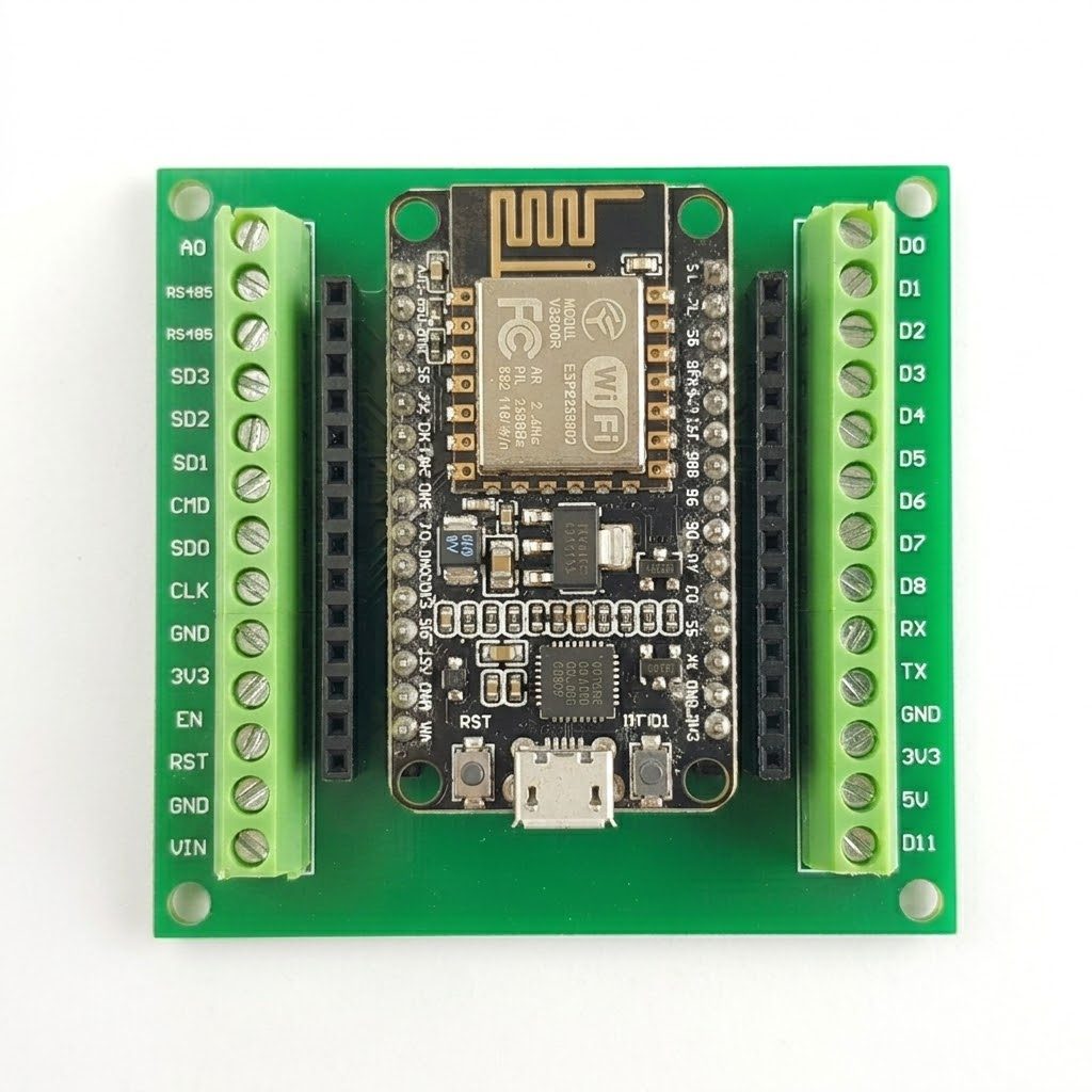
The board with the NodeMCU in the center and numbered screw terminals all around.
How to use a screw terminal
Three steps, always the same for every wire:
- Strip about 5 mm of insulation from the wire (with wire strippers or scissors)
- Insert the bare tip into the small hole above the terminal, all the way in
- Tighten the screw with the screwdriver — turn until the wire doesn't slip when pulled gently
⚠️ Do not tighten too hard: the screw is small. Tighten until the wire doesn't slip out, then half a turn more and that's it. Forcing it risks stripping the screw or breaking the wire.
Multiple 3V3 terminals and multiple GND terminals
On the board, you will find two or three 3V3 terminals and two or three GND terminals (these are "duplicated" pins). This is convenient: every sensor will need its own power and ground, and this way we don't have to "multiply" a single pin — just use a free terminal each time.
4. Step 1 — Place the NodeMCU on the board
It's the first concrete thing to do:
- Find the socket in the center of the board: two parallel rows of small holes ready to receive the NodeMCU pins.
- Align the orientation: the micro-USB port of the NodeMCU must face the side of the board where it says
USB(or, if your board doesn't have that label, the side where theD8,RX,TXterminals match the pins labeled with the same names on the NodeMCU). - Press gently: all pins must enter together. If you feel resistance, do not force it — lift, check the alignment, and try again.
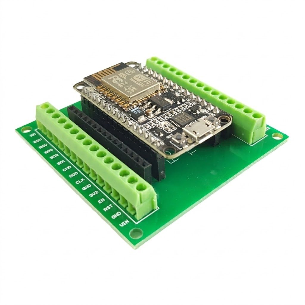
NodeMCU inserted with the USB port aligned with the board edge: visual confirmation of correct orientation.
⚠️ If you get the direction wrong, the NodeMCU won't work but usually won't break. To remove it: with a small flathead screwdriver, pry alternately from both sides, never just from one side (you risk bending the pins). Then rotate it 180° and reinsert.
Done. The board is ready to receive the sensors.
5. Step 2 — Connect the temperature probe
The DS18B20 probe has 3 wires coming out of the cable, of different colors (usually red, black, yellow — sometimes red, black, white: depends on the model).
| Wire Color | Goes to Terminal |
|---|---|
| Red | 3V3 (power) |
| Black | GND (ground) |
| Yellow (or white) | D5 (signal) |
Additionally, you must place the 4.7 kΩ resistor "as a bridge" between the red wire and the yellow wire. Without this, the probe will not respond — it is mandatory.
Step-by-step procedure
- Strip 5 mm from each of the 3 probe wires
- Red wire + one end of the resistor together in the
3V3terminal (both in the same terminal) - Black wire in the
GNDterminal - Yellow wire + the other end of the resistor together in the
D5terminal
💡 The resistor has no orientation: its two ends are the same. You can insert it however it's convenient.
⚠️ Without the resistor, the probe gives readings of "−127 °C" (meaning "no response"). This is the classic symptom — if you see that value in the dashboard, this is almost always the cause.
6. Step 3 — Connect the OLED display
The OLED display has 4 male pins along one side, with names printed on them: GND, VCC, SCL, SDA (the order varies between models — always check the printed labels, not the physical order).
| Display Pin | Goes to Terminal |
|---|---|
VCC |
3V3 |
GND |
GND |
SDA |
D3 |
SCL |
D4 |
Step-by-step procedure
You need 4 M/F jumper cables (one female end, the other male).
- Take 4 M/F jumpers. If you have a color set, use: red for
VCC, black forGND, yellow forSDA, green (or other) forSCL— it will be easier not to make mistakes when rechecking. - Insert the female side of the jumpers onto the 4 display pins (they fit directly, no stripping needed)
- Strip 5 mm from the male side of each cable
- Insert each cable into the corresponding terminal on the board, following the table above
💡 128×32 vs 128×64 Display: the JoyReef firmware is optimized for the 128×32 pixel model. The 128×64 might work, but some text may be cut off.
⚠️ Pay attention to the pin order on the display: on cheap models, the physical order of the 4 pins changes (some have
GND/VCC/SCL/SDA, othersVCC/GND/SDA/SCL). Always check the printed labels on the display, do not trust the position.
7. Step 4 — Connect the float switches
Float switches are switches that activate when the sensor's "float" touches the water. They have 2 wires and that's it — no polarity, the two wires are interchangeable.
| Float Switch | Signal Terminal | Common Terminal |
|---|---|---|
| #1 | D6 |
GND |
| #2 | D7 |
GND |
| #3 | D1 |
GND |
| #4 | D2 |
GND |
💡 Why this order? The numbers 1-4 correspond to those you will see in the portal (IN1, IN2, IN3, IN4). The firmware maps the order internally like this. You connect following the table, and in the portal, you will find exactly the correct numbering.
💡 What are the 4 float switches for? Typically: 2 for automatic top-off (low level + safety level in sump) + 2 for water change (fill tank and drain tank levels). You decide the precise configuration in the ATO guide — here you just need to connect them physically; assigning roles happens later from the portal.
Procedure for each float switch (identical for all 4)
- Strip 5 mm from the 2 float switch wires
- Insert any one wire into a free
GNDterminal on the board - Insert the other wire into the corresponding signal terminal (
D6for the first,D7for the second,D1for the third,D2for the fourth)
⚠️ No resistor for float switches. Unlike the DS18B20 probe, the "pull-up" is already activated internally by the firmware. If you add one on your own, the float switches usually stop working.
💡 Physical placement: for now, connect them "in the air" on the table to test the system. Once it works, you will mount them in the sump in the final position — the ATO guide explains where they go for top-off and where for water changes.
8. You've finished the assembly!
Well done, the physical part is complete. On your table you should have:
- ✅ NodeMCU inserted on the screw board
- ✅ DS18B20 probe with pull-up resistor
- ✅ OLED display connected (4 wires)
- ✅ 4 float switches connected (8 wires in total)
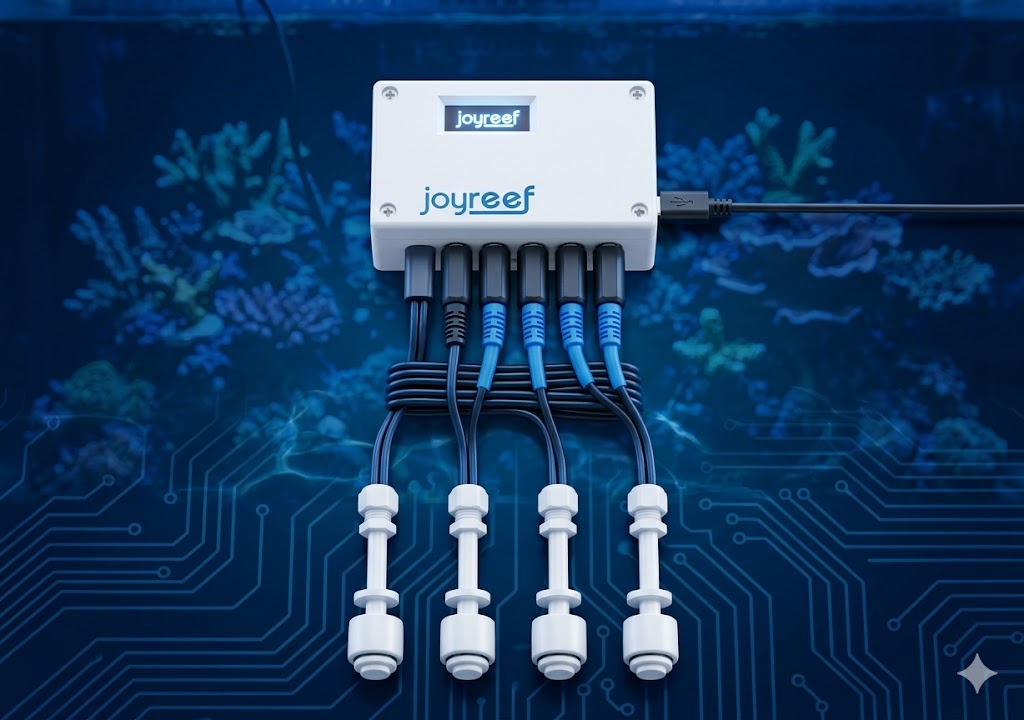
The finished controller with all sensors connected: finish line reached.
One important thing before turning it on
When you connect the USB cable and power the controller, do not expect the display to turn on or the float switches to respond. The NodeMCU fresh out of the box is "empty": it does not yet have the JoyReef software installed. Without software, even if the hardware is perfectly connected, nothing happens.
To bring it to life you must load the firmware — it's the step in the next guide.
⚠️ For now, do not connect the USB cable to the computer yet. Let's wait until we've read how to flash via the browser (it's the simplest way). If you connect now, Windows/macOS might install unnecessary drivers — better to do it in the right sequence.
9. Next step
Now that the hardware is ready, you need to:
- Load the software (firmware) onto the NodeMCU — it's the step that "teaches" it what to do with the sensors
- Connect it to your WiFi network and your JoyReef account
- See the first temperature reading appear on the dashboard
You can find all of this in:
📖 Guide 03 — Load the firmware and connect to WiFi (~15 min)
✅ Quick checklist before starting the next guide: you have (a) the controller assembled as above, (b) the micro-USB data cable, (c) a computer with Google Chrome or Microsoft Edge (Safari and Firefox do not work for flashing). If yes, you're ready.
Happy reefing!
JoyReef Guide · v1.0 · Questions? Write to us at supporto@joy-reef.com